
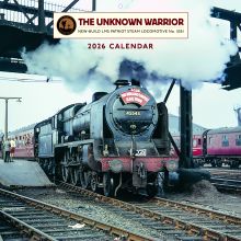
Reduced to £5.00 plus £2.50 p&p
Engineering Update - August 2021
Submitted by Kevin West on 16 September, 2021 - 15:10
Work on The Unknown Warrior has continued at a limited pace since the last report.
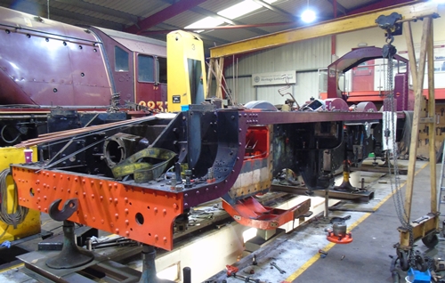
5551 in the West Shed 4th Aug 2021. Photo by Kevin West
The PRCLT engineers have continued to work on 5551 for one day a week over the period covered by this report. Work on 6233 Duchess of Sutherland is nearing completion. Test running is due during August with a return to the main line during the autumn. Once commissioning has been completed it will allow the engineers to return to work on 5551 over the coming months.
CHASSIS AND MOTION
Work undertaken at West Shed recently includes machining and fitting the Expansion Link Bearings.
Simon Scott is progressing work on the Expansion Link Bearings and Fittings. The inside assembly is being completed as time allows, with new fitted bolts for the mounting brackets made recently.
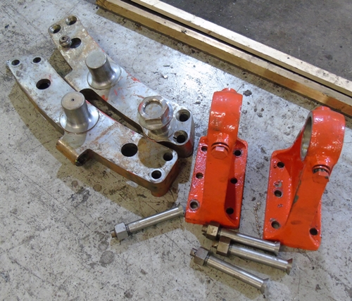
Inside Expansion Link parts. Photo by Kevin West
Machining of other fittings continues as time allows.
CYLINDERS
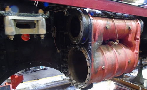
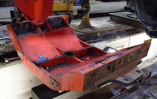
RH Cylinder being prepared for removal – 4th Aug 2021. Photo by Kevin West
The outside cylinders are being prepared for some work to install guide bars for the valve heads that were not shown on the original drawings used to produce the casting. The Guide Bars are narrow ribs in the centre chamber of the valve chest which support and guide the valve rings on the valve head through the centre chamber during the fitting or withdrawal of the valve assembly. The Guide Bars are shown on the original inside cylinder drawing and were included on the casting.
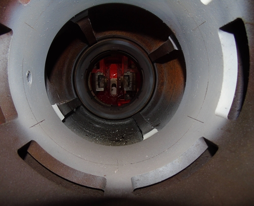
A view of the inside of the Inside Cylinder Valve Chest. The 4 Guide bars can be seen running between the Valve Liners. Photo by Kevin West
For some unknown reason they were not shown on the original drawing for the outside cylinders, so they were not included in the castings. PRCLT’s Simon Scott has plenty of experience in the maintenance of steam locomotive cylinders and strongly recommended that we add these features to our cylinders.
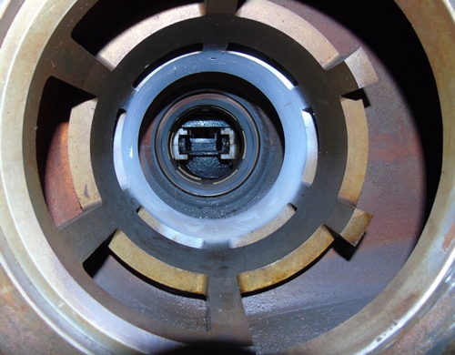
A view of the inside of the RH Outside Cylinder Valve Chest. Photo by Kevin West
A little pain now will reap great reward every time the valves are fitted or removed in the future. The only way to install these ribs is to weld them in place, but as the material is SG Iron (also known as Ductile Cast Iron) they have to be heated for the welding to take place and for that to be done they must be removed from the frames. Originally this was a disappointing thought, but now the left-hand cylinder has been removed it has revealed further issues that require attention. Without removing this cylinder we would probably not have discovered these points which would undoubtedly cause problems with the loco in service and required the loco to be stopped for repair.
The first issue concerns the surface finish of the main frames where parts are bolted or riveted. As supplied, the steel has a skin known as ‘mill scale’, which leaves an uneven surface. This is normally removed by either shot blasting or scraping to provide a smooth, flat surface for castings such as a cylinder block to be fitted hard up against the frame plate surface. Once the left-hand cylinder had been removed it is clear that this ‘mill scale’ has not been removed.
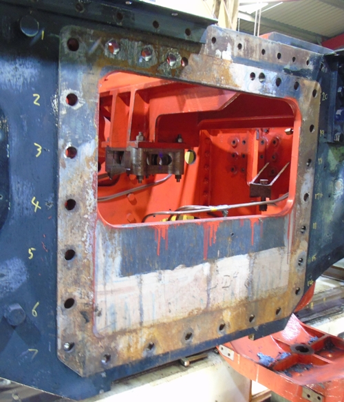
A view of the LH Main Frame following removal of the Outside Cylinder. The uneven surface when the Cylinder sat can be seen. Photo by Kevin West
As the lower cylinder bolts also locate the Bogie Pivot Stretcher to the inner faces, this has also been removed and revealed a similar condition with mill scale still on the frame surface. If left in this condition it could lead to the parts becoming loose and moving slightly as the locomotive runs. Over time this ‘fretting’ would get worse and result in vibration at least, and a failure at worst, in time.
The Bogie Pivot Stretcher following removal from the Frames. Photo by Kevin West
The right-hand cylinder is due to be removed imminently so the condition there will then be known. Having discovered this between the frames and the outside cylinders leads us to question if is it the same for the inside cylinder, stretchers, horn guides and all the other parts bolted to the main frames. The only way to find out is to remove the parts and check. At present the plan is to remove the front buffer beam, which is fitted with bolts anyway, so relatively easy to remove and then follow with the inside cylinder. This is necessary anyway as the second issue found concerns the fitted bolts used to mount the cylinders. A fitted bolt has a hexagonal or countersunk head, a precision turned shank and a threaded end section for a nut.
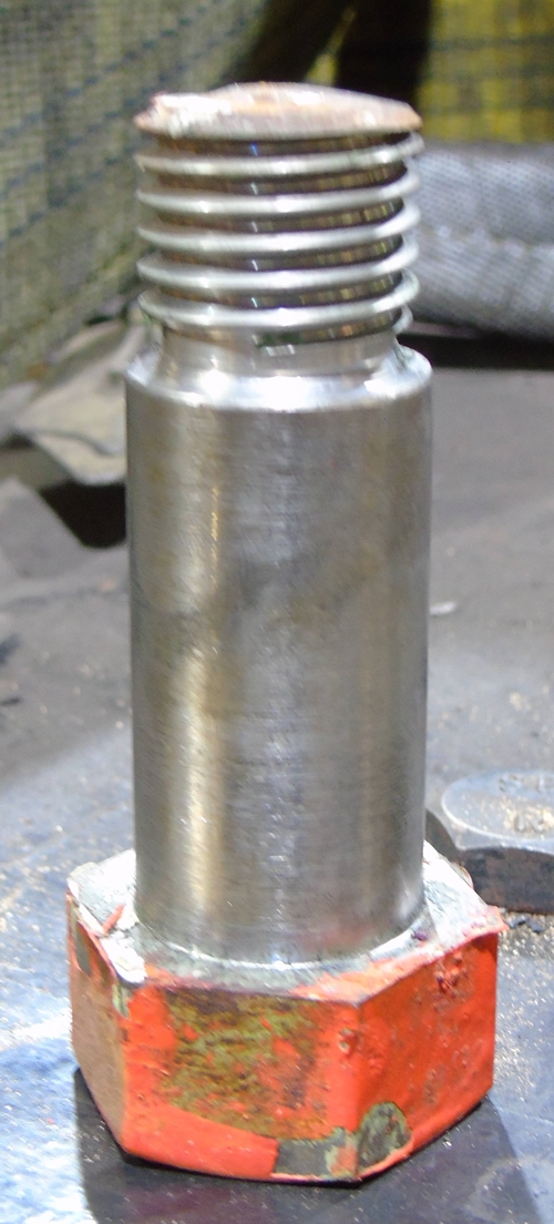
A Fitted Bolt following removal. Photo by Kevin West
The hole that the bolt is fitted into will be drilled through all parts and then reamed to be a smooth round hole of a known size. The shank of the bolt to go into the hole will be turned to be slightly larger than the hole by 3 or 4 thousandths of an inch. The bolt is hammered into the hole to provide a positive location, a nut fitted, tightened and then the nut may be stitch welded to the bolt to stop it rotating.
On 5551 we have found many cylinder bolts slightly smaller than the hole rather than slightly larger. As the left-hand cylinder was removed it was possible to just pull the bolts out instead of having to drive them out with a hammer. The combination of poor surface contact between cylinder and frames and poor bolt fitting could have resulted in the cylinder becoming loose in a very short time in service with major consequences for the locomotive.
We also had one fitted bolt that was a reasonable fit but the thread broke off as it was being punched out. This was due to the undercut between the thread and the shank being incorrectly machined with square corners instead of there being a radius in each corner. This square corner introduced a weak point that can lead to a failure such as happened to this bolt.
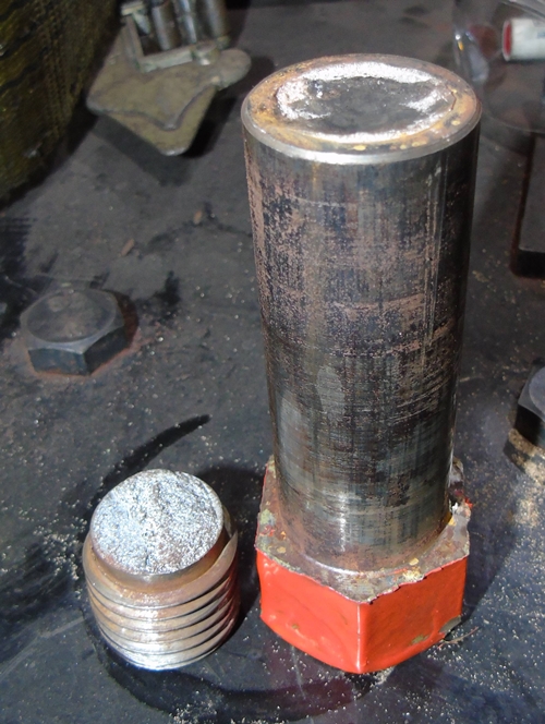
Broken Fitted Bolt. Photo by Kevin West
DRIVING WHEELS
The Driving Wheels have been consuming a large amount of our time over the last three months, but not for the reasons we wished.
Following on from the last report when we had found the right-hand trailing wheel to be badly cracked, a full inspection of the remaining five wheel castings was instigated. This entailed shot blasting to remove all of the paint and filler back to bare metal. This took longer to arrange than we had hoped and led to a slight delay before we could book the inspectors from British Engineering Services to undertake the required testing.
The inspection finally took place on 14th June in the presence of our engineering team and Nick Norton from The Boro Foundry, who supplied the original castings. The process entails using magnetic probes on the casting in the area to be tested. Once in position and powered up an aerosol spray which contains fine graphite particles is sprayed onto the casting surface. The magnetic field draws the graphite into any surface cracks which show up as lines on the surface. This only shows up the cracks on the surface, not details of the depth of any defect.
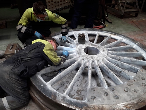
The inspection underway on the LH Trailing Driving Wheel. Photo by Kevin West
In summary all five castings have numerous cracks and surface defects both where the spokes join the centre hub and the outer rim. The number of, and the size of the defects are outside the acceptable maximum in the relevant standard for wheel castings.
We have examined if there is a possible repair method and/or an enhanced inspection regime that would be acceptable to the relevant approval bodies but this has been found to be not possible, so the only approach is to replace all of the six driving wheel castings. This is obviously a major disappointment and there are a lot of questions relating to how castings with so many defects were approved and allowed to progress as far as they did. Boro Foundry have started their own investigations and the wheel sets are due to be transported to their works (at no cost to the project), to aid this to be undertaken. The x-ray inspections that Boro had undertaken by an external contractor when the wheels were cast have been found to be poorly exposed and not capable of showing up any defects.
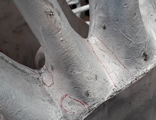
A view of one wheel with the surface cracks highlighted. Photo by Kevin West
The wheels testing was carried out by British Engineering Services. Their summary of the findings was reported as follows:
“When assessed against ASTM E125-63 a number of the discontinuities were found to exceed severity Level V which is the highest severity level within E125-63, Table 1 of BR170 only allows a maximum of Level III for linear discontinuities and that’s for the lowest quality level of casting…
…as the wheelsets are rotating mass these would be required to meet the highest quality level this would need to be confirmed with the regulatory body.
Most discontinuities were found to be linear in nature, hot tears and shrinkage which would be considered to be the most deleterious in future use.”
BOGIE
Work is continuing on the rework of the Bogie.
The next stage of this work is to complete all of the drawings required for the bogie as soon as possible.
LUBRICATION SYSTEM
Design work on the 16-feed mechanical lubricators awaits completion.
FITTINGS
Our Safety Valves that are being manufactured by Locomotive Maintenance Services of Loughborough are reported to be finished and awaiting testing and calibration.
BOILER
HBSS have now completed the installation of the firebox side stays. An order has been raised to cover installation of the Transverse Stays that run across the firebox above the inner firebox.
TENDER
The tender frames are close to completion at Leaky Finders with the rear buffer beam being fitted as this edition goes to press.
PAPERWORK
Work continues on locating paperwork.
APPROVALS AND CERTIFICATION
This task also continues.